Signal Processing and Analysis Tools for Civil Engineers

Back to Contents   


File System

The following file types are supported for storing time histories:

Other file types are also support in the software for different purposes:


1. LNEC's Test File Format - ltf

This is the recommended file type to store time histories because it can take advantage of most software features.

This file format supports time histories with different trigger time, time step and number of samples.

Read and save operations are supported.

The data stored is the following:


Header - 4 string fields (Name, Series, Date, Observations)


For each time history / channel:

  • Name;

  • Unit (e.g. mg, m, kN, Volts, etc);

  • Type (e.g. Acceleration, Displacement, etc);

  • Info - any information;

  • Trigger time - 128 bits absolute time

  • Time step

  • Time history data - stored with 16 bits of precision (65536 levels);

  • Channel ID String - String used to identify the hardware channel where the data was acquired;

  • Data format - raw units (e.g. Volts) or engineering units (EGU);

  • Scale Factor - between raw units and engineering units, [EGU/raw units];

  • Offset - between raw units and engineering units, expressed in raw units (e.g. V).

Note: The data of each channel can be presented in raw units or in EGUs has indicated in the "Data Format" field.


2. LNEC's Binary File Format - bin

This file format was intensively used in LNEC's seismic tests and is fully supported. It does not support time histories with different trigger time, time step and number of samples.

Read and save operations are supported.

The data stored is the following:

  • Name;

  • Scan rate [Hz];

  • Number of samples;

  • Time history data - stored with 16 bits of precision (65536 levels);

Note: The data of each channel is always transformed and presented in EGU. The data is stored in 16 bits where 32768 represents +10V and -32767 represents -10V, so changing the scale factor and offset to 1 and 0, respectively, the raw units are retrieved.


3. ASCII column ordered text files  - txt

Any ASCII file with the time-histories ordered in columns.

Read and save operations are supported.


4. GEOSIG's Seismic Recorders files - GSR

GEOSIG's Seismic Recorders, 12, 16 and 18 bits GSR files are supported. Please contact GEOSIG for more informations.

Only read operations are supported. The processed data should be saved in the LTF format (small loss of precession in the 18 bit format);

In the software is possible to retrieve the following information:

  • Instrument name;

  • Trigger date;

  • Trigger time;

  • Number of samples;

  • Sampling frequency [Hz];

  • Resolution [mg];

  • Time history data.

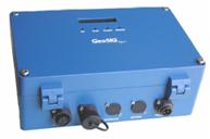
GEOSIG's Seismic Recorder


5. LNEC's Function File - lff

This is a binary file used to store functions. These file type can only be read/save in the Functions Manager Module;

Read and save operations are supported.

The data stored is the following:


For each function:

  • Name;

  • Info;

  • XType (e.g. Frequency);

  • XUnit (e.g. Hz);

  • YType (e.g. Phase);

  • YUnit (e.g. rad);

  • XValues, stored in double precision (64 bits);

  • YValues, stored in double precision (64 bits).

Note: Because the number of points in the functions are usually small (less than 100), there's no need to save them using a reduced precision format.


6. Math Channels Data Structure File - mc

This is a binary file used to store the data structure (levels and operations) to calculate math channels in the Math Channels Module;

The data stored is the following.

For each Level:

  • Type of operation (to individual channel or between channels);

  • Operation data (name, channels, parameters);

  • Channels out names;

  • Channels out units.

7. MDOF Model File - mm

This is a binary file used to store the data of MDOF models in the MDOF Model Module;

The data stored is the following:

  • DOF's height and weight and units;

  • DOF's mass and inertia and units;

  • DOF's acceleration channels and units;

  • DOF's displacements channels and units;

  • Output units.

8. Visualization Data File - vis

This is a binary file used to store the settings of 2D visualizations in the 2D Visualization Module;

The data stored is the following:

  • For each node: Coord_X, Coord_Y, Movement type, Rigid Body Shape and Points, XType, XChannel; XValue; DispXScale; YType; YChannel; YValue; DispYScale; ZType; ZChannel; ZValue; DispZScale;

  • For each line: i) Node 1 and ii) Node 2;

  • Movement's scale factor

9. Channels Configuration File - cc

This is a binary file used to store the channels configuration for acquisitions and outputs;

The data stored is the following:

  • For each acquisition channel:

    • Active (T/F);

    • Channel ID String - String used to identify the hardware channel where the data was acquired;

    • Name;

    • Type (e.g. Acceleration, Displacement, etc);

    • Unit (e.g. mg, m, kN, Volts, etc);

    • Data format - raw units (e.g. Volts) or engineering units (EGU);

    • Scale Factor - between raw units and engineering units, [EGU/raw units];

    • Offset - between raw units and engineering units, expressed in raw units (e.g. V);

  • For each output channel:

    • Active (T/F);

    • Channel ID String - String used to identify the hardware channel where the data was acquired;

    • Name;

    • Type (e.g. Acceleration, Displacement, etc);

    • Unit (e.g. mg, m, kN, Volts, etc);

    • Data format - raw units (e.g. Volts) or engineering units (EGU);

    • Scale Factor - between raw units and engineering units, [EGU/raw units];

    • Offset - between raw units and engineering units, expressed in raw units (e.g. V);


Last updated: 15-08-2006 19:16